The cotter passes through slots made in two coaxial parts and thus prevent the relative motion between them. The cotter in the cotter joints fails due to double shear.

Cotter Joint Mechanical Engg Diploma Simple Notes Solved Papers And Videos
Design of Cotter Joint to Connect Piston Rod and Cross head.

. Design of Cotter Joint - Free download as Powerpoint Presentation ppt PDF File pdf Text File txt or view presentation slides online. Socket and Spigot Cotter Joint. Calculate the diameter of each rod by Calculate the thickness of the cotter by the t empirical relationship given in Eq.
Keys Cotter and 55 COTTER AND COTTER JOINT Knuckle Joints A cotter is a metallic strip of uniform thickness but tapers in width. It is not suitable to connect rotating shafts which transmit torque. In such a type of joint the piston rod is tapered in order to resist the thrust instead of being provided with a collar for the purpose.
Joint between the piston rod and the crosshead of a steam engine. Design of rods For the rods under axial load Axial stress in the rods σ 4F πd2 STEP 2. The sleeve and cotter joint is shown in Fig.
Types of Cotter Joints. A Knuckle Joint is used for the application of the Tie rod joint of jib crane or Tension link in the structure of the bridge. Let P Load carried by the rods d Diameter of the rods d1 Outside diameter of sleeve d2 Diameter of the enlarged end of rod t Thickness of cotter l Length of cotter b Width of cotter a Distance of the rod end from the beginning to the cotter hole.
T031 d Calculate the diameter d 2 of the spigot on the basis of tensile stress. 2Sleeve and cotter joints. It is not used to connect the shafts that are rotating or transmitting torque.
Sleeve and Cotter Joint. Elemental analysis at various loads. A view looking from socket end.
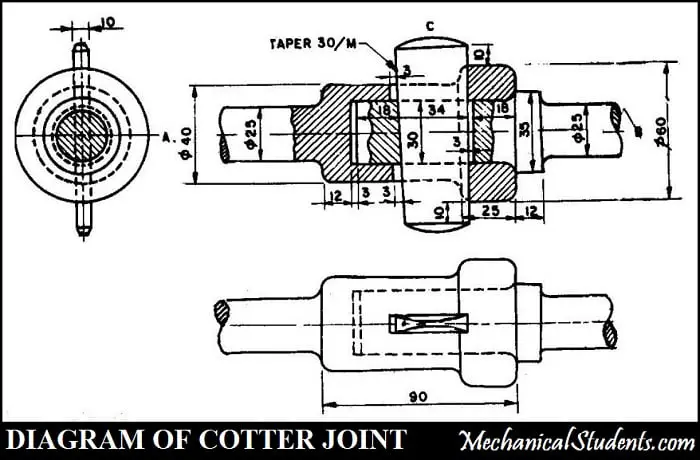
DESIGN OF COTTER JOINT. Design of cotter joint. SOCKET AND SPIGOT COTTER JOINTS Draw the following views of an assembled Socket and Spigot Cotter Joint to 11 scale assuming the diameter of the rods d20mm.
The cotter joint to connect piston rod and cross head is shown in Fig. Design of Sleeve and Cotter Joint. Design of Socket and Spigot Cotter Joint.
Gib and Cotter Joint. Department of Mechanical Engineering BIET Davanagere 57004. Front view in half section 2.
Cotter and Knuckle Joints431469. Design of cotter joint. TYPES OF COTTER JOINTS 1Socket and spigot cotter joint.
Meshing of cotter joint using ANSYS R15. In this article I am going to present a detailed explanation of the design procedure for Knuckle Joint and Cotter Joint. P So the methodology of the study includes 1.
100 but may be as large as 1. WHAT IS A COTTER JOINTS A cotter is a flag wedge shaped piece of steel. Cotter joint uses one or two cotters to connect two rods rigidly transmitting forces and motion with no rotation of the rods 3.
CAD Model of cotter joint assembly. The taper may be very small like 1. DESIGN PROCEDURE FOR COTTER JOINT The basic procedure to calculate the dimensions of the cotter joint consists of the following steps.
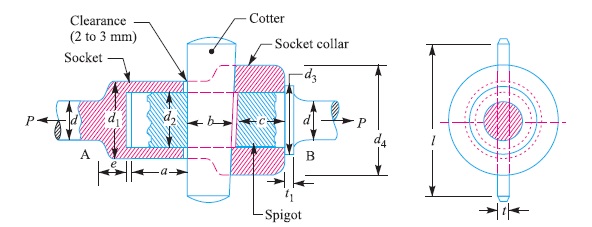
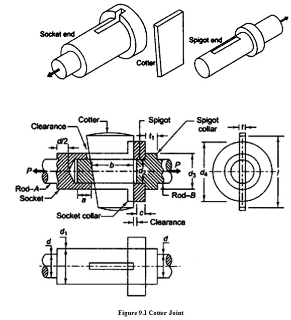
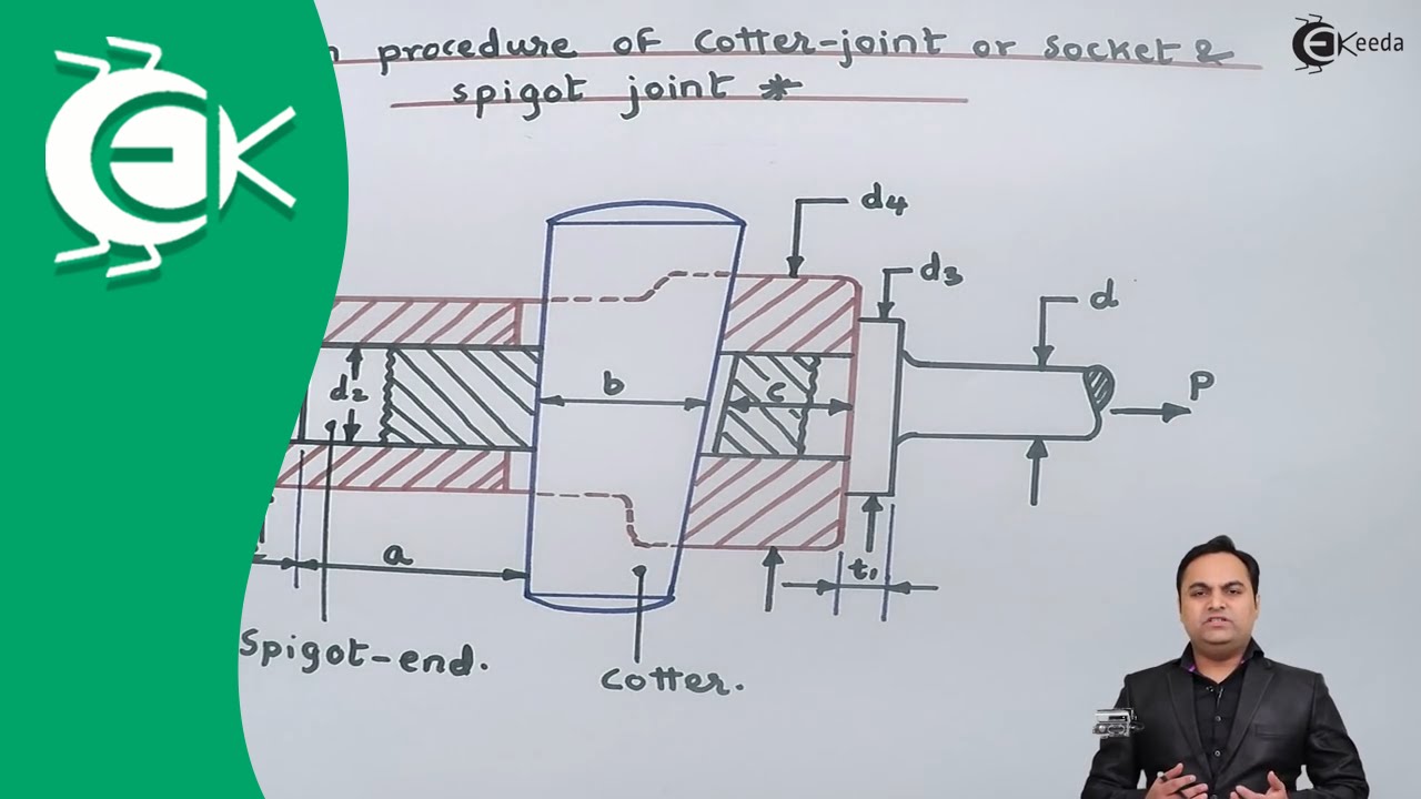
1 Design of Cotter Joint to Connect Piston Rod and Cross head. A cotter joint is used to connect the two shafts which are either subjected to tensile or compressive axial force. DESIGN PROCEDURE OF COTTER JOINT Notations used in design are as follows P Load on the joint or pull acting on rods d Diameter of the rod d1 outer diameter of socketd2 Diameter of spigot or inside diameter of socket d3 Outside diameter of spigot collard4 Diameter of socket collar t1 Thickness of spigot collar a Distance from the.
Design of Gib and Cotter Joint for Strap End of a Connecting Rod. Design of Sleeve and Cotter Joint. Axes of the rods to be joined should be collinear.
Design of the cotter. 3Gib and cotter joints. CAD Model of cotter joint using CATIAV5R20.
Cotter joint is used to connect two rods subjected to axial tensile or compressive loads. Design of the spigot and the Cotter a Crushing strength of the cotter Fd1tσc b Axial stress across the slot of the rod σ 4F πd1 24d 1t STEP 3. The cotter joint is withstanding the load applied during the working condition or not.
There is no relative angular movement between rods. Joints like screwed joint cotter joint sleeve cotter joint universal joint or knuckle joint 1The Knuckle joint is a type of joint which is used in steering system in between the steering rod and pinion of the steering gear as the line of the action axis of both the mechanical parts are intersecting and lies in different planes so it is.
Pin On Cad
Socket And Spigot Cotter Joint And It S Design Engineers Gallery
Machine Design Lesson 9 Design Of Cotter Joint
Design Procedure Of Cotter Joint Socket And Spigot Joint Design Of Machine Youtube
Design Procedure For Knuckle Joint Cotter Joint Formulas Pdf

31 Cotter Joint Final Pdf Computer Aided Design Autodesk

Gate Ese Lesson 9 Design Of Cotter Joint Offered By Unacademy

Design Of Cotter Joint Pdf Cotter Joint A Cotter Joint Is Used To Connect Rigidly Two Co Axial Rods Or Bars Which Are Subjected To Axial Tensile Or Course Hero
0 comments
Post a Comment